Our next assignment is to create a game based on contraptions. Its schedule is as follows!!
8th January - Create a Wiki space.
12th January - Survey of games by Bhairav and team.
18th January - Design of Interface to be submitted.
23rd January - Script of the Game
7th February - Modeling of Objects
14th February - Texturing of Objects.
21st February - Lighting
7th March - Game Engine and scripting
28th March - Rendering Starts
5th April - Testing of game
15th April - Final Product
Another requirement is that of a place to upload unlimited number of files . I am currently looking into that and put up that site link here on the blog.
Till then,
Kaeyur
Saturday, January 10, 2009
Wednesday, January 7, 2009
Meeting
This is just to remind everyone that we are meeting in IIT on Thursday at 11 am in the morning.
Till then,
Cheers!!
Kaeyur
Till then,
Cheers!!
Kaeyur
Tuesday, January 6, 2009
Spot Light
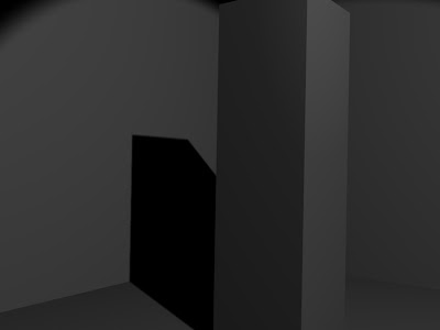
While working on Assignment 2, that is about Spot light. When i started with the assignment i first thought, i should know how spot light works, than it will be easy to continue with assignment. So this is about how Spot light works, casting shadow and its different parameters few of them i have earlier mention in my previous post.
Casting Shadow :
In Materials Button
Materials which should cast shadow must be set with the "Shadow" button ON. By enabling this button, Blender calculates the shadow cast by this
object.
Materials which should receive the shadow of another object should have the "Shadeless" button set OFF. By enabling this button , Blender won't cast shadow over this object.
In Lamp Buttons
The only lamp type that can be used for casting shadow is Spot.
The Spot lamp should have the "Shadows" button set to ON then Soot light can cast shadow and light.
The spot lamp could be set to "Only Shadow" if there is another light in the scene. The Spot then ONLY cast shadow but not the light.
The default blender lamp is the lamp which doesn't cast shadow,so to cast shadow we have set at least one light source as a SPOT. Among all the types of lamps, the SPOT is the only light source that can cast shadows.
In Render Button
The shadow button should be set to ON.
Basic
In order to calculate shadow, Blender uses the shadow buffer algorithm, that is the scene is rendered from the point of view of spot and that Blender calculates which object is placed before the other on its line of sight, thus defining which pixels,"hidden" from the spot view by anyone object, will receive shadow in the final render.
If there are many Spots in the scene, Blender ''renders ' the scene as many times, from each Spot point of view, and store the result in its shadow buffer.
After this we deal with different parameters which we have to set individually.

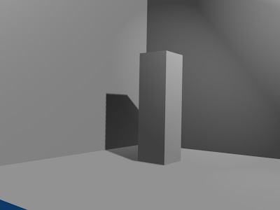
1. Spot of the shadow buffer (Bufsi)
As i have said before, information about pixels that get light or shadow is stored in a buffer, which acts exactly the same a rendered picture. This means that shadow buffer has its own resolution. By default Blender's buffer size is 512x512 pixels
here u have just taken a rectangular solid to explain changes in parameter which effect shadow casting.
 this is with Bufsi=512
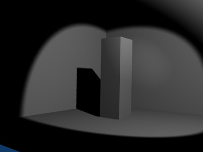
 this is with Bufsi=2048
as we can see changes very clearly, in first image the shadow is blocky, i mean the borders are not perfect it dissolves into small blocks, which doesn't give perfect outline. in second we have increase Butsi to 2048 and there is perfect outline to the shadow.
When we increase the Buffer Size, the shadow gets more accurate borders, which is better for close shot of an object and its shadow. Butsi behaves exactly as the resolution of a render picture does.
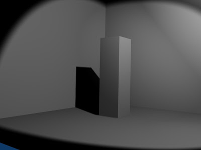
2. Size of the Spot(SpotSi)
The angle beam of Spot also has a great effect on the look of your shadow.
i am increasing light energy to 1.5 so we can have a little bit bright look and changing Butsi and Spotsi.
 with default value, SpotSi=45, Shadow buffer size=512
 SpotSi=120, Shadow buffer size=512
 SpotSi=60, Shadow buffer size=2048
Casting Shadow :
In Materials Button
Materials which should cast shadow must be set with the "Shadow" button ON. By enabling this button, Blender calculates the shadow cast by this
object.
Materials which should receive the shadow of another object should have the "Shadeless" button set OFF. By enabling this button , Blender won't cast shadow over this object.
In Lamp Buttons
The only lamp type that can be used for casting shadow is Spot.
The Spot lamp should have the "Shadows" button set to ON then Soot light can cast shadow and light.
The spot lamp could be set to "Only Shadow" if there is another light in the scene. The Spot then ONLY cast shadow but not the light.
The default blender lamp is the lamp which doesn't cast shadow,so to cast shadow we have set at least one light source as a SPOT. Among all the types of lamps, the SPOT is the only light source that can cast shadows.
In Render Button
The shadow button should be set to ON.
Basic
In order to calculate shadow, Blender uses the shadow buffer algorithm, that is the scene is rendered from the point of view of spot and that Blender calculates which object is placed before the other on its line of sight, thus defining which pixels,"hidden" from the spot view by anyone object, will receive shadow in the final render.
If there are many Spots in the scene, Blender ''renders ' the scene as many times, from each Spot point of view, and store the result in its shadow buffer.
After this we deal with different parameters which we have to set individually.

This is the originally view without changing any parameter.
1. Spot of the shadow buffer (Bufsi)
As i have said before, information about pixels that get light or shadow is stored in a buffer, which acts exactly the same a rendered picture. This means that shadow buffer has its own resolution. By default Blender's buffer size is 512x512 pixels
here u have just taken a rectangular solid to explain changes in parameter which effect shadow casting.
 this is with Bufsi=512
 this is with Bufsi=2048
as we can see changes very clearly, in first image the shadow is blocky, i mean the borders are not perfect it dissolves into small blocks, which doesn't give perfect outline. in second we have increase Butsi to 2048 and there is perfect outline to the shadow.
When we increase the Buffer Size, the shadow gets more accurate borders, which is better for close shot of an object and its shadow. Butsi behaves exactly as the resolution of a render picture does.
2. Size of the Spot(SpotSi)
The angle beam of Spot also has a great effect on the look of your shadow.
i am increasing light energy to 1.5 so we can have a little bit bright look and changing Butsi and Spotsi.
 with default value, SpotSi=45, Shadow buffer size=512
 SpotSi=120, Shadow buffer size=512
 SpotSi=60, Shadow buffer size=2048
The smaller angle of beam is, the sharper the borders of the shadow are. Before setting the BufSi to any higher value, first enhance the quality of your shadows by setting the SpotSi value as small as possible.
3. Samples
Here if we dont to set Buffer size too high, for that we can use samples (default value 3). Without increasing Buffer size too high we can give a smooth outline to shadow by increasing samples value.
4.Only shadow and Energy Button
we used Spot to cast both shadow and light. Because of that we can see spot light on both floor and walls. If we want to dissiciate shadows from light source it can be done. Instead of putting Spot light, put few hemi or lamp, after getting proper light in the scene, put Spot light, in which turn ON "Only Shadow" button. After this Spot will only cast shadow and it wont add any light to the scene.
The shadow deepness increases dramitically in order to compensate this, we can change the energy value of the spot.
 Spot energy=1
 Spot energy=1.5
5. Soft
This defines the size of the area being sampled. the higher the value, the smoother the border of the shadow. In all previous renderings, Soft was set to 3. using a low soft value like 3 is perfect most of the time.
6. Bias
sometimes strange patterns appear in the shadow area. To prevent this, set Bias to the highest value possible like 5.
7. Clipsta and clipEnd
These two parameter set how light and shadows are dealt with in the Spot vicinity. They are visualized by apink segment running along the spot direction. Every face of any mesh closer to the Spot than the Clipsta value has light, and the every face of mesh beyond the ClipEnd value has shadows. Any face of mesh between these two has its pixels given a light or shadow value according to the data stored into the shadow buffer.
1. set the range between Clipsta and ClipEnd the smallest possible.
2. set the Clipsta highest possible.
Final conclusion
1. try to set Spotsi within 45 and 60 degree, avoid setting above 90 degree.
2. set samples to 5.
3. try to set BufSi to 700 to 1024.
4. set the range between clipsta and clipEnd thye smallest possible, set clipsta the higest possible.
5. set soft to 3.
6. set Bias to 5.
This is all about casting shadow with Spot light, working and its parameters.
Nitin Ayer.
Friday, November 21, 2008
Break
Hey all,
since our exams are coming up from the 3rd of december, we will be going on a break. As per my best knowledge, the last exam is on the 29th for Gokul,Karan and Priyam. For Chirag, Nitin and me i.e Kaeyur, the last one is on the 7th of January!.
Till then, best of luck to all
Cheers,
Kaeyur
since our exams are coming up from the 3rd of december, we will be going on a break. As per my best knowledge, the last exam is on the 29th for Gokul,Karan and Priyam. For Chirag, Nitin and me i.e Kaeyur, the last one is on the 7th of January!.
Till then, best of luck to all
Cheers,
Kaeyur
Thursday, November 13, 2008
Second Assignment...
hi everyone...
about second assignment, its done...i showed render images to gokul and he replied....that's what we have to do...actually when he explained me about the assignment i didn't understand completely that what we want ? and after that he told me to start with a spot light and how in auditorium a spot light works, create that in blender u will come to know about it...
now about how to create that...follow the steps....
first create the studio like re size the default cube and delete the three front phases like this....

and after that add a new cube adjust the light source and than add a lamp as a spot light, in default it will look like this....

render image....

render image without additional light source.....

the spot light in its default setting, we can see the a light spot around the object but we don't know where is the light source exactly place and we cant even see the light rays on the studio wall also....
now press F5 and go to LAMP BUTTONS, in LAMP BUTTONS go to SHADOW AND SPOT and enable halo button and render the current frame...

about second assignment, its done...i showed render images to gokul and he replied....that's what we have to do...actually when he explained me about the assignment i didn't understand completely that what we want ? and after that he told me to start with a spot light and how in auditorium a spot light works, create that in blender u will come to know about it...
now about how to create that...follow the steps....
first create the studio like re size the default cube and delete the three front phases like this....

and after that add a new cube adjust the light source and than add a lamp as a spot light, in default it will look like this....


render image without additional light source.....

the spot light in its default setting, we can see the a light spot around the object but we don't know where is the light source exactly place and we cant even see the light rays on the studio wall also....
now press F5 and go to LAMP BUTTONS, in LAMP BUTTONS go to SHADOW AND SPOT and enable halo button and render the current frame...

in this render image u will get answers of are previous doubts, about source of light and light rays on studio...
as you can see in the render image there is a gap between spot of light and light cone....

as you can see in the render image there is a gap between spot of light and light cone....

here we cant remove this by changing the intensity or by resizing the cone of spot light in any of the axis....in this we can even change the halo intensity, i mean intensity of light cone, even that wont work here...
for this light cone to extend further more and to fill that gap, i tried many things, i have put spot light through different angle,changing intensity , resizing , i search about it on google but didn't got anything but than some how i just change the distance and it worked...the thing we never used up till now...in lamp BUTTONS go to lamp, besides the name of lamp there is a panel called distance....change the distance and u can extend the light cone without resizing it any scale...so here is the final render image...here distance is 31 (default value is 20)

now with some little bit of changes, put light source at some angle....

and render image...

so this is all about assignment 2....
Nitin Ayer
Nitin Ayer
Saturday, November 8, 2008
Problems in making a video
while making a video in game engine (the one which i posted last time with cube), cube falling down on a plane...on cube i have put different pictures...
but while making this video i came across few problem some of them i solved like i tried to make make video and i started animating all 250 frames are done and than i saw avi output but it has nothing than i i came to i didnt recorded in IPO and...
another problem cube was falling ion a plane, i gave cube as a dynamic substance and plane as static but when cube was falling down it intersects the plane at some extends and than it stops like this....

i dont knw why this is happening and in avi output the background in dark orange is that is permanant or we can change ? and how?
when we are working on blender simultaneously one dos file is also running, when i was making video i was watching how many frames are done in dos file after few frames i just watched the video in that instead of red colour i got blue and in dos file this message appeared
Detected GL_ARB_texture_env_combine
Detected GL_ARB_texture_cube_map
Enabled GL_ARB_multitexture
Enabled GL_ARB_vertex_program
Detected GL_ARB_depth_texture
Detected GL_EXT_separate_specular_color
shaders not supported!
after every animation it was saying "shaders are not supported !"
than i found it was because of graphic card and graphic cheapset of motherboard it will occur because of those cheapset who doesnt support open GL graphic system....so if any buying new graphic card make sure about open GL system....
and new version of blender is out version 2.48a, in 2.48 there were some bugs in game engine....
so if anyone knows about plane and cube intersecting problem than please inform me...
Nitin Ayer
Assignment
Assignment:- to place different picture on each sides of cube...
this assignment is done here are the steps to do it....


Once you have the edges selected, click ctrl-e to bring up the edge menu and mark the selected edges as a seam.

after this we need to save this unwrap cube for this in UV Image Editor click on UVs button and than select script......

a new panel will open in this we can change the size from default 512 size and than click on ok and than give the file name and path to save UV FACE LAYOUT it will save this layout in .tga format convert it into .jpeg and than place the pictures in the unwrap cube using any image editor like photoshop....

now i have this jpeg file and i want wrap this around cube again...

now to wrap this image again on cube go to UV Image Editor and in image option click on open and than select the image and open it...and after this go to texture paint mode and u can see image wrap on the cube.........


and now if we want to place different picture than in unwrap image we can place are images.....
but now the problem what i came across when i was placing picture was that if disturb the size of unwrap image from 512 to something else while placing the picture....you want be able to wrap that image back on cube....
next one is while saving .tga file if you save it as standard 512 resolution u cand add image of bigger resolution like of 800 or 1600...because it disturbs the resolution of unwrap image...and after that we cant wrap it around cube again....so u need to use the image of same resolution what you have selected earlier....

i was supposed to make video of this but i couldnt make it because one problem that is next post so for now this assignment is done...and i am starting with second one...
Nitin Ayer
this assignment is done here are the steps to do it....
The first thing we need to do is bring up the UV Image Editor. Usually we want this displayed at the same time as our cube. We can accomplish this by splitting the display area. To do this, right-mouse click on the top of the display area (where the resize cursor is visible) and selecting “Split Area”.
Once you split the display, you’ll want to set one of them to display the UV Image Editor. Once you’ve got the UV Image Editor displayed, it should look something like this:

The first map we’re going to create is the simplest - one image for all sides of the cube. To set this up we first need to switch the cube’s display to the “UV Face Select” mode. this mode is not available in blender new version 2.48a it was there in in version 2.45...but to work with this select "Texture paint mode" and then come back to edit mode.

When you enter "edit mode" , you’ll notice the display o
n the left turn blue. This represents all the faces on your UV map. You’ll want to make sure all your faces are selected. You can do this by hitting the ‘a’ key on the cube display a couple of times. ‘a’ will select and deselect all items on your current display. When the faces are selected, the UV map will be blue, if nothing is selected, the display will be black.

Now that our UV map is set up, we can give it an image. take an 512x512 resolution image and open the image in UV Image Editor

open the image in edit mode after opening image go back texture paint mode there u will see the image applied to all the faces of cube....

If you render this scene, you might notice your texture doesn’t show up yet. That’s because the material hasn’t been told to use it. This is configured in the materials menu and click on "texface" button and now render

One image for all the sides of the cube is good and all, but usually I want a different image on each side. To do this, we’re going to have to “unwrap” the sides of the cube onto our UV map. Unfortunately, Blender has no idea how to unwrap an object - even one as simple as a cube. We have to give it a little help by defining some seams.
for this go back to edit mode and select edge selection mode and deselect all the edges by pressing a key

Once you have the edges selected, click ctrl-e to bring up the edge menu and mark the selected edges as a seam.

After the seam has been created, select entire cube in edit mode and got to UV Image Editor and click on UVs button and than unwrap the cube...


after this we need to save this unwrap cube for this in UV Image Editor click on UVs button and than select script......

a new panel will open in this we can change the size from default 512 size and than click on ok and than give the file name and path to save UV FACE LAYOUT it will save this layout in .tga format convert it into .jpeg and than place the pictures in the unwrap cube using any image editor like photoshop....

now i have this jpeg file and i want wrap this around cube again...

now to wrap this image again on cube go to UV Image Editor and in image option click on open and than select the image and open it...and after this go to texture paint mode and u can see image wrap on the cube.........

now render image

and now if we want to place different picture than in unwrap image we can place are images.....
but now the problem what i came across when i was placing picture was that if disturb the size of unwrap image from 512 to something else while placing the picture....you want be able to wrap that image back on cube....
next one is while saving .tga file if you save it as standard 512 resolution u cand add image of bigger resolution like of 800 or 1600...because it disturbs the resolution of unwrap image...and after that we cant wrap it around cube again....so u need to use the image of same resolution what you have selected earlier....
now i have made one this is the unwrap image....sorry i didn't had better picture of size 512

and this is actual cube........

and this is actual cube........

i was supposed to make video of this but i couldnt make it because one problem that is next post so for now this assignment is done...and i am starting with second one...
Nitin Ayer
Subscribe to:
Posts (Atom)