Dear all,
You can download the .blend files of the movie: BBB..from here:
http://graphicall.org/bbb/index.php
It would be worth downloading them and our hands on them!!!
-Sameer
Thursday, September 24, 2009
Wednesday, September 23, 2009
Tutorial for sectioning a mesh with nodes
This is from the Blender wiki:

 Adding a cube
  Selecting a pivot
  Selecting a texture type
  Setting up the colorband
  Adding a cylinder for the Z axis
 Colors setup for all three cylinders.
  Initial node setp
  Adding nodes
  Final node setup
  Section passing along the Y axis with the default mapping
  Section rotated about the Z axis
 Trashadow enabled
  Two sections applied to the same material
  Node setup for more than one section
In this tutorial we will create a section passing through a simple object using material nodes. We'll then have a look at various ways of combining several sections into more complex cut-outs, useful for, for example, architectural sections.
- Note
- This node set-up was originally described in this thread on the Blender Artists forums. The Cross Section script might also be of interest.
Simple set-up
Add a cube

In top view (Num7), add a cube (Space>Add>Mesh>Cube).
Just to make this simple object slightly more interesting, let's rescale it twice. Rotate (MMB drag) your view to see what you are doing. Under the 3D view, make sure "Median point" is selected as pivot and "Move object centers only" next to it is disabled.
Still in edit mode with everything selected, scale along the X axis (S>X>3), and along the Y axis (S>Y>2).

Create the section texture

Tab into object mode. Go to the material menu (F5) and click "Add new". Accept the default material and name.
- Then go to the texture menu (F6), click "Add new" and rename the texture "Section". Select Blend as material type and in the Color tab activate Colorband.
- The colorband we are going to create will serve as a mask that we are going to map onto the cube later. To get a crisp sharp section through the cube, we just need to move the two default colors to the center of the colorband in order to get a black transparent half and a white opaque half. So, move the left color to Pos 0.5. leave it black. Select the right color (change Cur:0 to Cur:1). move it to Pos 0.5 and change the color to White.

Three axes for visualisation

To make it easier to orient ourselves later, we'll add three cylinders representing the three coordinate axes in the render outputs.
Note: In the example below all three cylinders are made a single object. This is not necessary of course. If you prefer to make them three separate objects, just tab into object mode before copy-rotating them. Then follow the instructions below. If you make them three separate objects you can also skip the vertex group part below; just assign materials to each separate object. |
- In object mode and in top view, add a cylinder (Space>Add>Mesh>Cylinder) with, say, 16 vertices. As above, rescale it (S, Shift+Z, 0.1) (S, Z, 5).
- Copy-rotate it to create an X axis (Shift+D, R, Y, 90).
- Repeat to create a Y axis (Shift+D, R, Z, 90).

Let's create three vertex groups for these cylinders and add three simple materials to them.
- Go to the edit menu (F9). Still in edit mode, deselect everything (A). Place the mouse over the first Z-cylinder and hit L to select all linked vertices. In the Link and materials submenu, add a new vertex group, name it "Z", and hit Assign. Add a new material index, change its color to blue, and hit Assign.
- Deselect everything and repeat as above for the X and Y cylinders. Make them red and green respectively.
- Go to the material menu again (F5). In the Links and pipeline submenu, use the "3 mat 3" button to select the newly created materials and rename them Blue, Red, and Green respectively.
Node set-up


Now let's set up the nodes.
- First lets open the node editor. Assuming you are using the default Blender layout, in the top menu select the Material screen (or simply Ctrl+→). Open the node editor in one of the subwindows using the button in the lower left corner. All you will see at this time is a grey area, but don't worry. Open the material menu (F5) if not open already.
- Select the cube. In the Links and Pipeline subwindow click Nodes to activate nodes for this material and ZTransp to activate transparency.
- Drag (G) the Material and Output nodes and place them on the right part of the area. In the material node, select the material.
- On the left side, add a geometry input node (Space>Add>Input>Geometry).
- Add Mapping node (Space>Add>Vector>Mapping). It should automatically be connected to the Global connector of the Geometry node.
- Add a Texture node (Space>Add>Input>Texture). Use the tiny box to select the "Section" texture.
- All nodes are set up now. Connect the texture node's Value output to the Output node's Alpha input to complete the node system.

Moving the section around


Press F12 to render the scene. With the default settings in the mapping node, the section is passing along the Y axis. You can easily change this in the mapping node. Move the section along the axes by changing the value in the three top boxes. Rotate the section about the axes using the middle row. In my case I had to change the Z rot value to -135 to make the section face the camera.
 |  |
Note: Keep in mind that the mapping moves the section before it rotates it. So, if you change the rotation first, moving the section can then lead to non-intuitive results. Additionally, geometrically our section is an endless plane, so rescaling it or moving it in some directions, is not going affect the result.
[edit] Improving the setup

As you can see the inside of the cube is dark, as are the parts of the cylinders passing through the cube. Let's change this.
- With the cube still selected, in the shaders submenu enable TraShadow. This will allow transparent shadows to be cast on the inside of the cube.
- Select the cylinder object, and for each material enable TraShadow.
- If you want to make the cylinders all bright, disable Shadow for each material.
Adding more than one section

To add several sections,
- Copy the mapping and texture nodes. Plug the Global output of the geometry node into the second mapping node.
- Change the orientation of the second series of nodes. In the example given, the section was rotated 90 degrees about the Z axis.
- Add a mix node, and plug both texture nodes' color output into it.
- Add the value output of the first texture node into the Fac input of the mix node.
- Finally plug the mix node into the Alpha input of the ouput node.

Using different mix modes
 |  |
More complex sections can be achieved by using combinations of different mix modes.
Here are two simple sections through a building. The first is passing along the X axis and the second along the Y axis.
These two simple sections can be combined into more interesting outputs using several methods.
 |  |
With Multiply the values of both sections get multiplied. If one or both sections are black/transparent the resulting output is zero or transparent. Therefore, only the part of the building shared by both sections remains visible.
With Difference the values from both sections are subtracted from each other and the absolute value is returned. The resulting output is the parts of the building unique to either of the sections.
 |  |
Finally, by plugging these two outputs into a third mix node set to Add, both outputs are combined into a single section.
To make the cut-out even more interesting keep adding sections using different mixing modes.
Here the previous output is combined with a third horizontal section. By choosing Multiply the transparency of this third sections cancels out the previous result making the top of the building transparent.
Converting .blend files to .exe directly in Blender
Create a new folder and copy into it the dll's from the Blender Installation folder. On Windows it would be under C:\Program Files\Blender Foundation\Blender. Copy the required dll's (link to the list provided at the end) into the folder).
Then open Blender. Click on File>Save Runtime. Save as .exe into the folder you just created. Aand you're done.
The method is OS dependent though. Doing this on Windows will produce an exe that is only Windows compatible. The required DLL's need to be in the same folder as the .exe for smooth functioning.
[edit] It slipped my mind that Nitin had worked on this earlier and had given a presentation quite some time ago. For some reason it wasn't posted here and I searched it again. My apologies for not mentioning him.
To run the .exe in fullscreen, Go into to the scene menu (F10) and on the far right you will see "Game Frame Settings" click that, another menu will appear and there will be a button saying "Fullscreen".
[edit] The complete list of the required dll's can be found here.
Then open Blender. Click on File>Save Runtime. Save as
The method is OS dependent though. Doing this on Windows will produce an exe that is only Windows compatible. The required DLL's need to be in the same folder as the .exe for smooth functioning.
[edit] It slipped my mind that Nitin had worked on this earlier and had given a presentation quite some time ago. For some reason it wasn't posted here and I searched it again. My apologies for not mentioning him.
To run the .exe in fullscreen, Go into to the scene menu (F10) and on the far right you will see "Game Frame Settings" click that, another menu will appear and there will be a button saying "Fullscreen".
[edit] The complete list of the required dll's can be found here.
Mouselook
Another tutorial posted by Ninja Goliath on the Blenderartists forum.
How do work the famous "Mouselook"
script used in most blender games ?
first of all, here are The basics of MouseLook :
The MouseLook script first involve, of course, the mouse ! !
!
but how ?
simple : while in-game, when you move your mouse, it's actually really moving
the mouse right in front of you. You just can't see it cuz it's hidden by default.
but if you could see it, you would see it stick pretty much at the middle of
your screen because the Mouselook code do Try to stick your mouse at the middle
of your screen every 1/60 seconds.
Thus, during 1/60 second, you can actually move your mouse from a few pixels.
If you do so, during the next "game engine computation" = after about 1/60 seconds,
the mouselook script will look at your mouse's position and say :
0.5 - I musn't jerk !
1 - OMG !!!
2 - The mouse isn't at the middle of the screen !!!"
3 - I must rotate the camera from a corresponding value !! ARGARGRG !!!
4 - Put back this cursor at middle of the screen !!!
And that's exactly how every single mouselook of the entire community works (AFAIK)
They just use different syntax and differents way of codeing it.
but OVERALL, they're pretty much all the same.
K, now you probably want to know how the heck you code this hein ?
Well here we go :
STEP 0.5 : Don't jerk plz !
This "0.5" step isn't really a step since it's only there
to put the mouse in the middle of the screen the first time the script run.
(SO that your screen doesn't jerk or so.)
(Delete that part of code and you'll quickly see why it's quite required :wink: )
The associated code is :

STEP 1 : OMG !!!
This is the common initialization of a script. It is the way
to include the sensors/actuator/owner object/properties into your code

Notice we import the "Rasterizer" module. (At line 8 )
This is to be able to use the mouses related functions
(to get the mouse position in our case and to stick it at the middle of the screen)
The above script will need the following setup (At least) to work
Because if it can't find a property/sensor/actuator it's looking for,
the script will crash in your face.

Notice that, in this script, we also set the "Mouse sensitivity".
This is the constant used to reduce the rotation (In number of pixels)
gathered from the mouse's position into a realistic amount of rotation.
STEP 2 : Where's the mouse ??
This step involve 2 different parts of codes :
The related function :
(Note that it's where the "init script" is contained.)

The related code :

The line "#86" involve the "moseMouve()" function which look for the
mouse's position and store it in the variable used to call the code
(the info is stored into the "move" variable in our case)
The lines 89 & 90 calculate the x & z rotation from the informations
stored into the "move" variable and with the mouse sensitivity.
STEP 3 : Rotate the camera ! ARGARGRG !!!
Here is the quite simple script who take care of this :

For more info, you can alway look into the API for the "applyRotation" function.
It's really simple as you can see.
I would only specify that we use the prefix "owner.parent" for the Z axis's rotation
instead of the common "owner" relating to the fact that, in the code, the owner is
actually the camera and it's parent is the player. Thus, the player only
rotate to left and right (Z axis) and the camera rotate up-down (X axis).
STEP 4 : Put back the cursor at middle of the screen !!!

That's all :P
Here's the overall code :
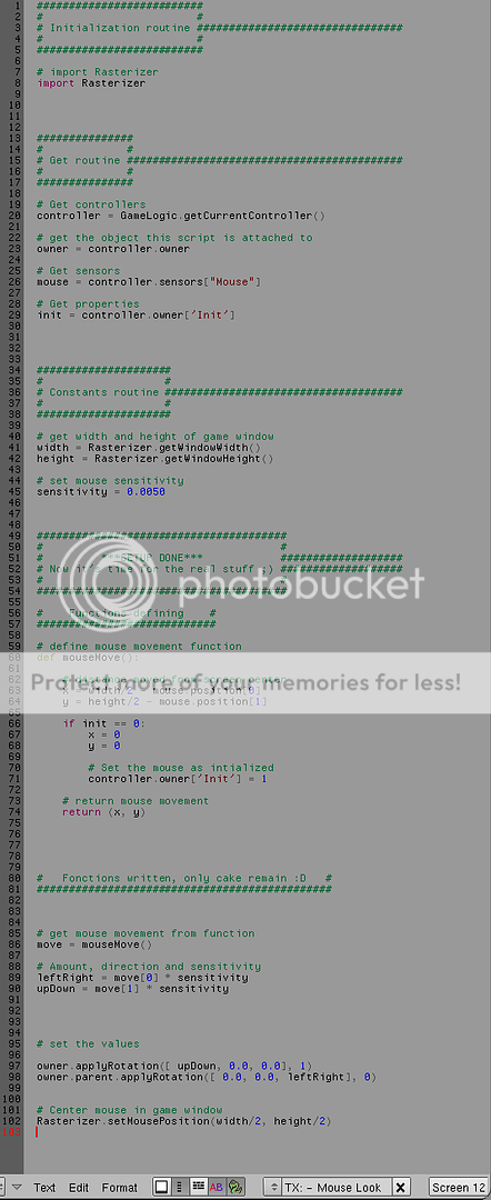
my own code is pretty much the exact
same as this except that it "CAP" the camera.
& there's a tricky setup so that the camera move smoothly.
How do work the famous "Mouselook"
script used in most blender games ?
first of all, here are The basics of MouseLook :
The MouseLook script first involve, of course, the mouse !
!but how ?
simple : while in-game, when you move your mouse, it's actually really moving
the mouse right in front of you. You just can't see it cuz it's hidden by default.
but if you could see it, you would see it stick pretty much at the middle of
your screen because the Mouselook code do Try to stick your mouse at the middle
of your screen every 1/60 seconds.
Thus, during 1/60 second, you can actually move your mouse from a few pixels.
If you do so, during the next "game engine computation" = after about 1/60 seconds,
the mouselook script will look at your mouse's position and say :
0.5 - I musn't jerk !
1 - OMG !!!
2 - The mouse isn't at the middle of the screen !!!"
3 - I must rotate the camera from a corresponding value !! ARGARGRG !!!
4 - Put back this cursor at middle of the screen !!!
And that's exactly how every single mouselook of the entire community works (AFAIK)
They just use different syntax and differents way of codeing it.
but OVERALL, they're pretty much all the same.
K, now you probably want to know how the heck you code this hein ?
Well here we go :
STEP 0.5 : Don't jerk plz !
This "0.5" step isn't really a step since it's only there
to put the mouse in the middle of the screen the first time the script run.
(SO that your screen doesn't jerk or so.)
(Delete that part of code and you'll quickly see why it's quite required :wink: )
The associated code is :
STEP 1 : OMG !!!
This is the common initialization of a script. It is the way
to include the sensors/actuator/owner object/properties into your code
Notice we import the "Rasterizer" module. (At line 8 )
This is to be able to use the mouses related functions
(to get the mouse position in our case and to stick it at the middle of the screen)
The above script will need the following setup (At least) to work
Because if it can't find a property/sensor/actuator it's looking for,
the script will crash in your face.
Notice that, in this script, we also set the "Mouse sensitivity".
This is the constant used to reduce the rotation (In number of pixels)
gathered from the mouse's position into a realistic amount of rotation.
STEP 2 : Where's the mouse ??
This step involve 2 different parts of codes :
The related function :
(Note that it's where the "init script" is contained.)
The related code :
The line "#86" involve the "moseMouve()" function which look for the
mouse's position and store it in the variable used to call the code
(the info is stored into the "move" variable in our case)
The lines 89 & 90 calculate the x & z rotation from the informations
stored into the "move" variable and with the mouse sensitivity.
STEP 3 : Rotate the camera ! ARGARGRG !!!
Here is the quite simple script who take care of this :
For more info, you can alway look into the API for the "applyRotation" function.
It's really simple as you can see.
I would only specify that we use the prefix "owner.parent" for the Z axis's rotation
instead of the common "owner" relating to the fact that, in the code, the owner is
actually the camera and it's parent is the player. Thus, the player only
rotate to left and right (Z axis) and the camera rotate up-down (X axis).
STEP 4 : Put back the cursor at middle of the screen !!!
That's all :P
Here's the overall code :
my own code is pretty much the exact
same as this except that it "CAP" the camera.
& there's a tricky setup so that the camera move smoothly.
Subscribe to:
Posts (Atom)